
 Handwielen, handslingers
 Knoppen, vleugelmoeren
 Klemhendels, verstelbare handgrepen
 Beugelgrepen, handgrepen
 Vaste, draaiende handgrepen
 Bedieningselementen
 Indicatoren, klokhandwielen
 Blokkeerbouten, drukstukken
 Machine elementen
 Koppelingen
 Stelvoeten, stelelementen
 Scharnieren
 Vergrendelingen, deursluitingen
 Snelspanners, spansluitingen
 Hydrauliek componenten
 Buisklemverbindingen
 Wielen en zwenkwielen
 Magneten
 Transportband componenten
 Lineaire bewegingscomponenten
 Trillingsdempers
 Aluminium profielen
 Vacuüm componenten
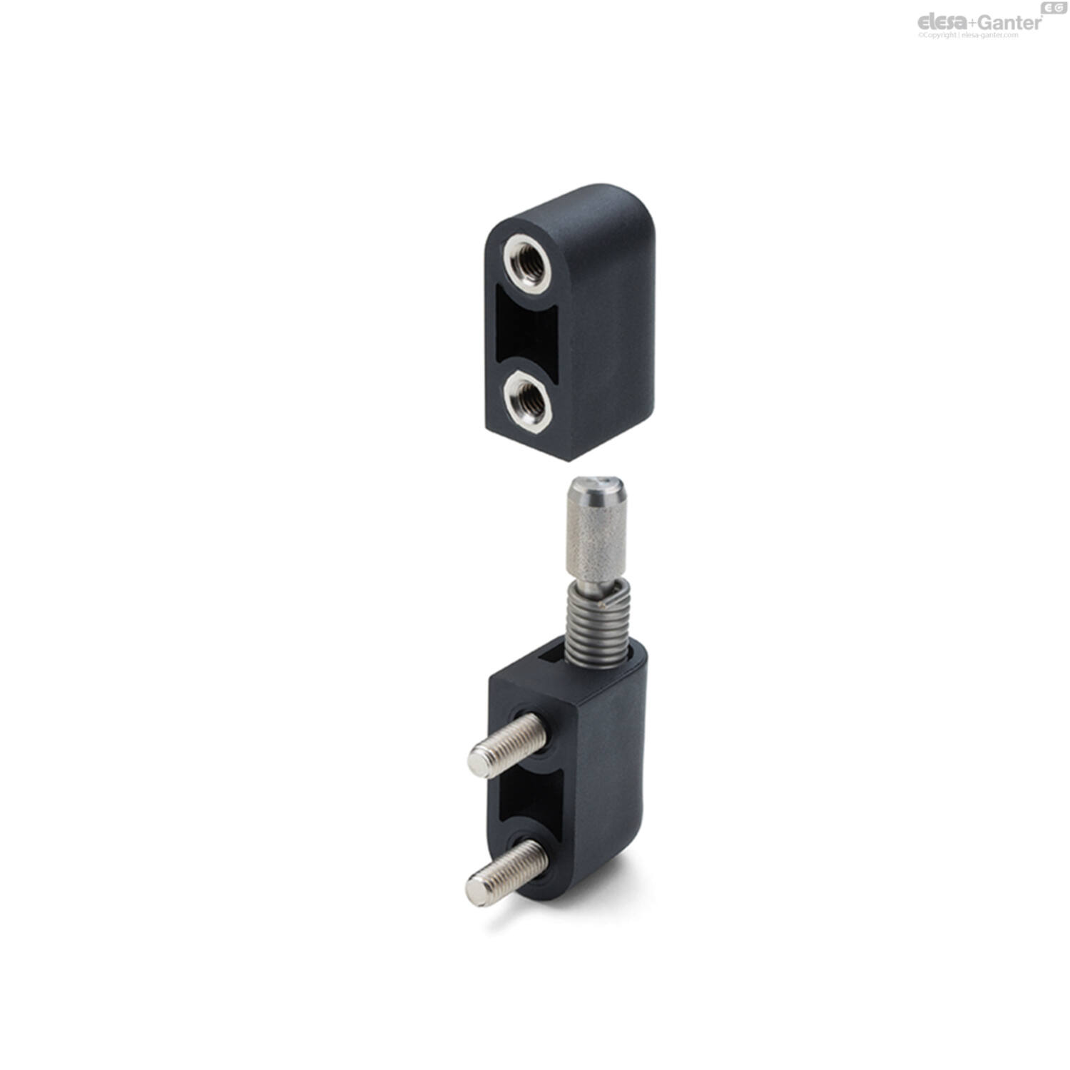









Omschrijving
Material
Glass-fibre reinforced polyamide based (PA) technopolymer, colour black, matte finish.
Pin
AISI 303 stainless steel.
Spring
Stainless steel spring.
Standard executions
Door closing return, left spring winding (see Fig.1):
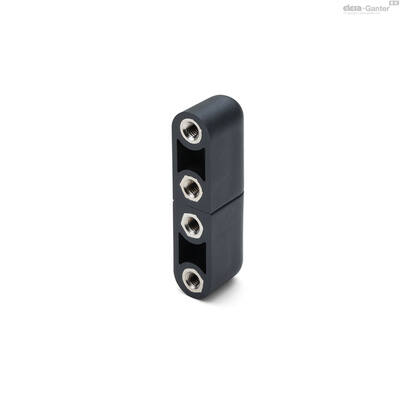
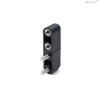
- CFNR-B-S: nickel-plated brass bosses with threaded hole.
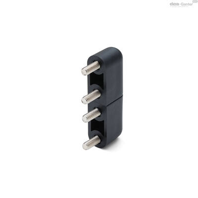
- CFNR-p-S: nickel-plated steel threaded studs.
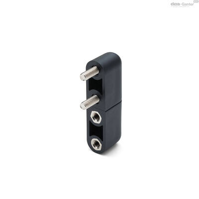
- CFNR-B-p-S: nickel-plated brass bosses with threaded hole (mounting on jamb side) or nickel-plated steel threaded studs (mounting on door side).
- CFNR-p-B-S: nickel-plated steel threaded studs, (mounting on jamb side) and nickel-plated brass bosses with threaded hole (mounting on door side).
Door opening return, right spring winding (see Fig.1):
- CFNR-B-D: nickel-plated brass bosses with threaded hole.
- CFNR-p-D: nickel-plated steel threaded studs, right spring winding.
- CFNR-B-p-D: nickel-plated brass bosses with threaded hole (mounting on jamb side) or nickel-plated steel threaded studs (mounting on door side).
- CFNR-p-B-D: nickel-plated steel threaded studs, (mounting on jamb side) and nickel-plated brass bosses with threaded hole (mounting on door side).
Features
The CFNR hinge has a built-in spring system (Elesa patent) for automatic return of the door when closing or opening.
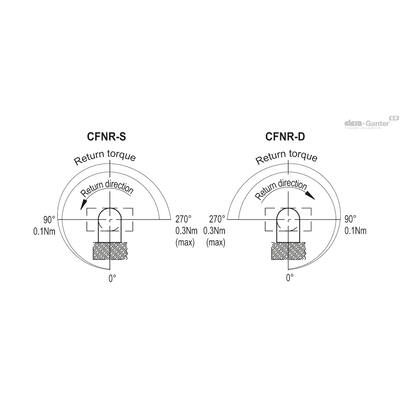
A pin is fixed in the hinge body which holds a spring in position with a maximum closing or opening return torque of 0.30 Nm at 270°.
The torque varies progressively with the opening/closing angle of the hinge.
In specific fatigue stress tests, the return spring exceeded 15,000 cycles while maintaining the same unaltered torque value.
The maximum weight of the door with two hinges installed which allows the return of the spring is 5Kg. This value is indicative as it is the result of tests carried out on a laboratory structure measuring approximately 0.7 m x 0.7 m.
It is recommended to always check the correct operation for the intended application.
They can be installed on folded sheet metal box doors.


| Resistance tests | |||
| Axial Stress | Radial Stress | ||
 |  |  |  |
| Parallel planes | Perpendicular planes | Parallel planes | Perpendicular planes |
| Maximum working load Ea [N] | Maximum working load Er [N] | ||
| 600 | 100 |
The deformation of the hinge at loads higher than the operating ones indicated here are such as to modify the geometry of the hinge itself, compromising its functioning.
Assembly instructions
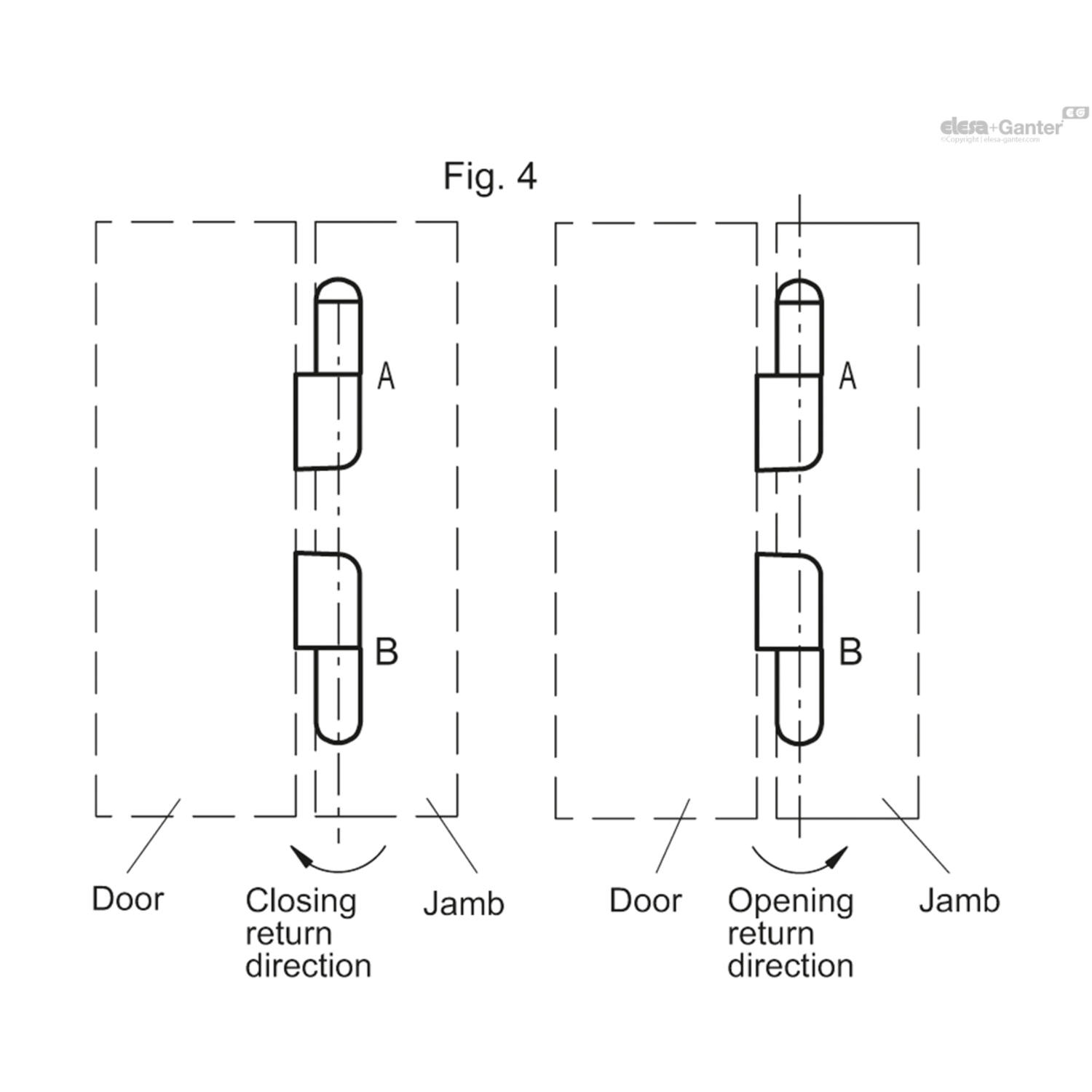
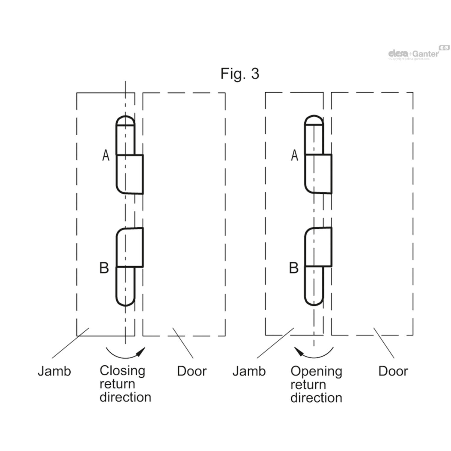
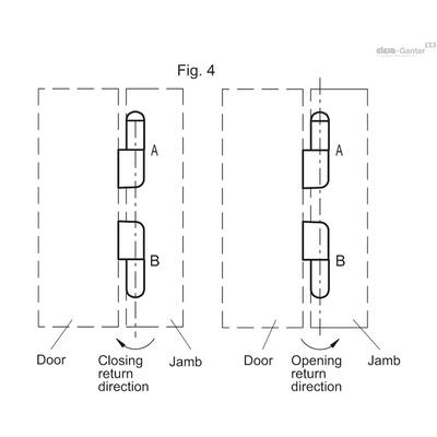
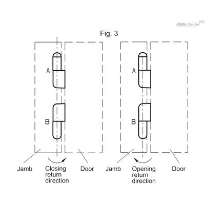
Based on the position of the jamb with respect to the door and the desired functionality, select the hinges necessary for positions A and B by selecting the correct suffix.
- Install the hinge body with the rotation pin on the jamb, preloading the hinge by 90° before locking the body on the surface.
- Use screws to fix the door to the second hinge body.
| Jamb position | Desired function | Positioning of hinges | |
| Position A | Position B | ||
| To the left of the door (Fig.3) | Closing spring return | CFNR-D-030 | CFNR-S-030 |
| Opening spring return | CFNR-S-030 | CFNR-D-030 | |
| To the right of the door (Fig.4) | Closing spring return | CFNR-S-030 | CFNR-D-030 |
| Opening spring return | CFNR-D-030 | CFNR-S-030 |

Accessories
To facilitate the 90° preloading operation of the hinge and its assembly on the door, it is possible to use the tool MT-CFNR (See Fig.2): which keeps the hinge in the preloaded position during installation.

Uitvoering
| Filters resetten | Filter: | ||||
Code |
Product omschrijving |
Aantal |
Prijs |
Bestel |
CAD |
|---|---|---|---|---|---|
| 470178117 | CFNR.65 B-M5-D-030 |
|
|||
| 470178116 | CFNR.65 B-M5-S-030 |
|
|||
|
|
|
|
|
|
|
|
|
|
|
|
|
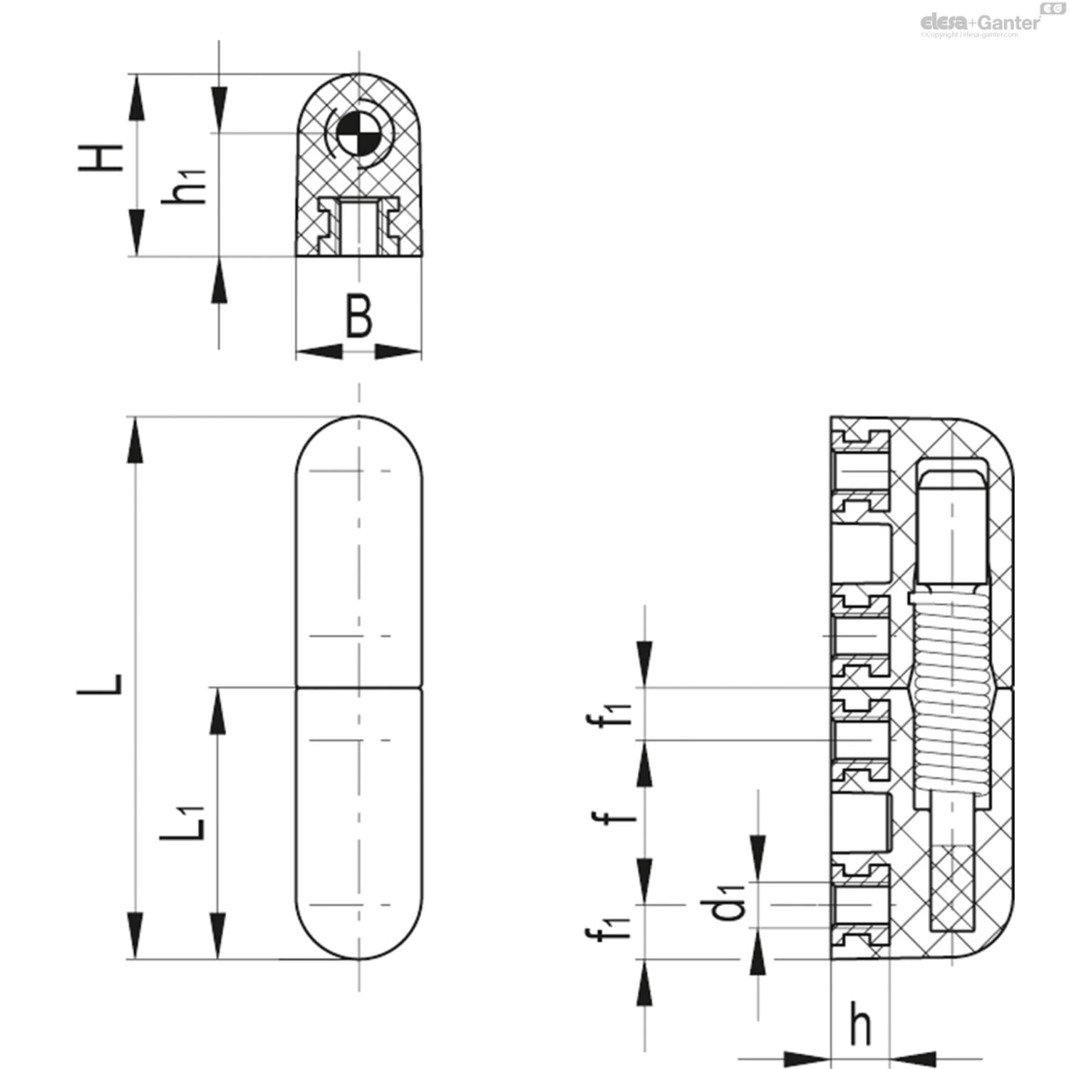
L |
h |
f |
Gewicht (g) |
L1 |
d1 |
f1 |
h1 |
B |
C#[Nm] |
H |
|---|---|---|---|---|---|---|---|---|---|---|
| 62 | 8 | 19 | 39 | 31 | M5 | 6 | 14 | 14.5 | 5 | 21 |
| 62 | 8 | 19 | 39 | 31 | M5 | 6 | 14 | 14.5 | 5 | 21 |