
 Handwielen, handslingers
 Knoppen, vleugelmoeren
 Klemhendels, verstelbare handgrepen
 Beugelgrepen, handgrepen
 Vaste, draaiende handgrepen
 Bedieningselementen
 Indicatoren, klokhandwielen
 Blokkeerbouten, drukstukken
 Machine elementen
 Koppelingen
 Stelvoeten, stelelementen
 Scharnieren
 Vergrendelingen, deursluitingen
 Snelspanners, spansluitingen
 Hydrauliek componenten
 Buisklemverbindingen
 Wielen en zwenkwielen
 Magneten
 Transportband componenten
 Lineaire bewegingscomponenten
 Trillingsdempers
 Aluminium profielen
 Vacuüm componenten



Omschrijving
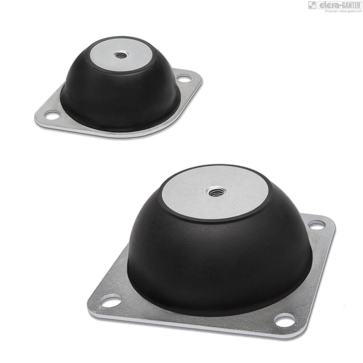
Vibration-damping body
Natural rubber NR, black colour.
- DVE: hardness 40, 60 Shore A ±5.
- DVE-SST: hardness 60 Shore A ±5.
Standard executions
- DVE-A: zinc-plated steel oval mounting flange, base plate and tapped boss.
- DVE-SST-A: AISI 304 stainless steel oval mounting flange, base plate and tapped boss.
- DVE-B: zinc-plated steel square mounting flange, base plate and tapped boss.
- DVE-SST-B: AISI 304 stainless steel square mounting flange, base plate and tapped boss.
Features and applications
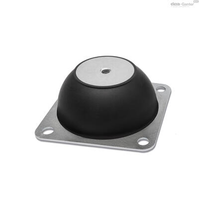
DVE vibration-damping elements are composed of two metallic elements joined together by a rubber anti-vibration body. A round element with a boss with a threaded pass-through hole constitutes the base for fixing the vibrating machine. Another element, oval or square shaped, constitutes the flange for fastening to the floor.
Generally used for applications with rotary machines that do not present big dynamic imbalances, where elasticity is required both vertically and transversely.
They are therefore very suitable for use with compressors, fans, vibrating feeders, rotary pumps or electric motors.
Vibrations can cause:
- malfunctioning and reduction of the machine lifespan and/or of the adjacent ones;
- noise and thus also damage to human health.
Load diagrams for each single code are available on request.
Special executions on request
- AISI 304 stainless steel elements and NR natural rubber with hardness 40 tolerance ± 5 Shore A.
- Executions with AISI 316 stainless steel mounting flange, base plate and tapped boss.
- Executions with NR natural rubber with different hardness.
|
|
|
|
|
|
|
|
|
|
|
|
|
|
|
|
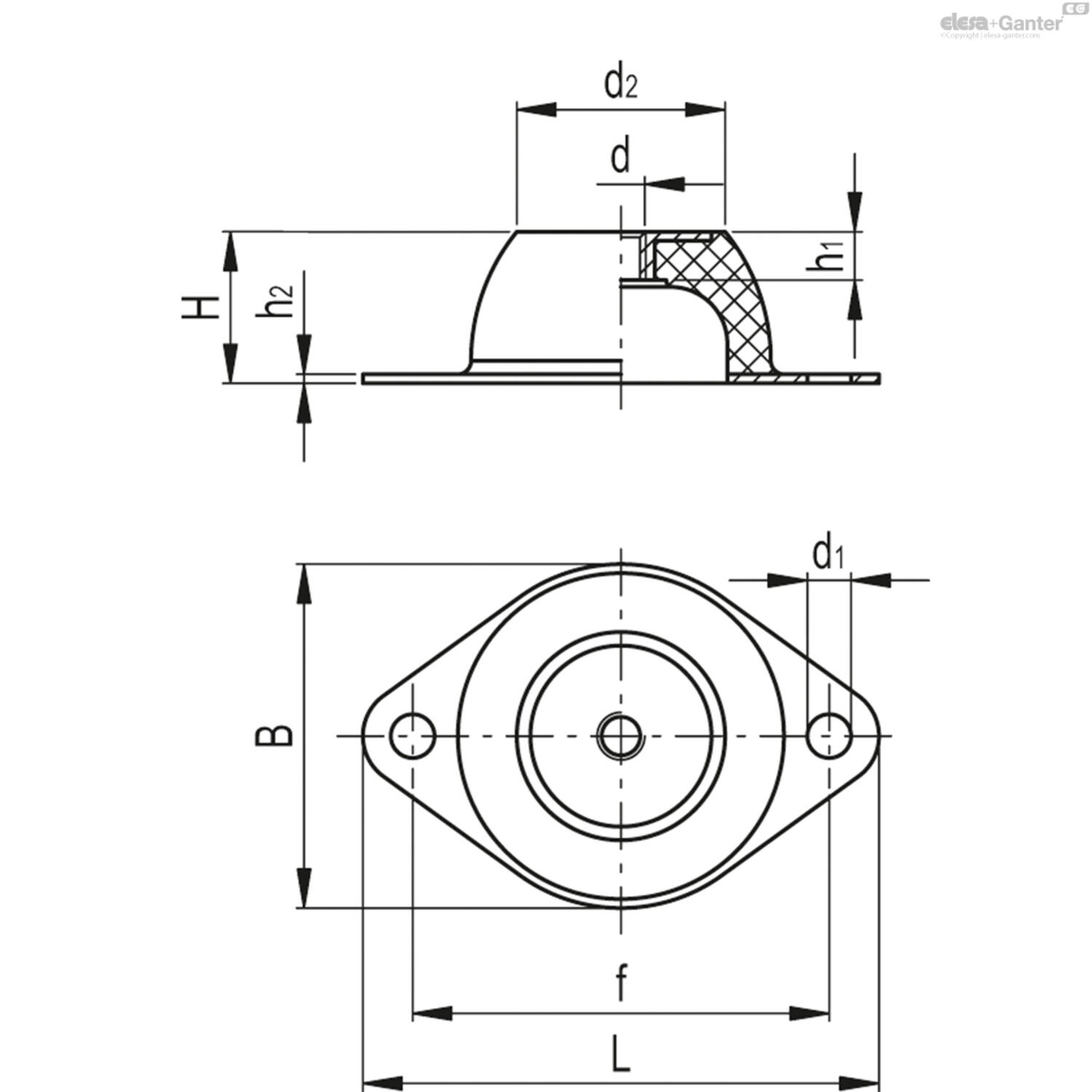
h2 |
L |
d2 |
D1 |
f |
Gewicht (g) |
d |
Stijfheid unit |
d1 |
h1 |
B |
max afbuiging |
H |
max belast.eenheid |
|---|---|---|---|---|---|---|---|---|---|---|---|---|---|
| 2 | 64 | 18 | n.v.t. | 50 | 30 | M6 | 13 | 7 | 7 | 43 | 5 | 20 | 62.5 |
| 2 | 64 | 18 | n.v.t. | 50 | 30 | M6 | 28 | 7 | 7 | 43 | 5 | 20 | 141 |
| 2 | 64 | 18 | n.v.t. | 50 | 30 | M6 | 28 | 7 | 7 | 43 | 5 | 20 | 141 |
| 2 | 85 | 33 | n.v.t. | 66 | 70 | M8 | 60 | 8 | 9 | 56 | 6.25 | 25 | 378 |
| 2 | 85 | 33 | n.v.t. | 66 | 70 | M8 | 103 | 8 | 9 | 56 | 6 | 25 | 617 |
| 2 | 85 | 33 | n.v.t. | 66 | 70 | M8 | 103 | 8 | 9 | 56 | 6 | 25 | 617 |
| 2 | 114 | 45 | 10 | 92 | 160 | M10 | 73 | 10 | 11 | 76 | 8.75 | 35 | 643 |
| 2 | 114 | 45 | n.v.t. | 92 | 160 | M10 | 157 | 10 | 11 | 76 | 8.75 | 35 | 1374 |
| 2 | 114 | 45 | n.v.t. | 92 | 160 | M10 | 157 | 10 | 11 | 76 | 8.75 | 35 | 1374 |
| 2 | 136 | 53 | n.v.t. | 110 | 265 | M10 | 86 | 11,5 | 11 | 96 | 10 | 40 | 855 |
| 2 | 136 | 53 | n.v.t. | 110 | 265 | M10 | 231 | 11,5 | 11 | 96 | 10 | 40 | 2307 |
| 2 | 136 | 53 | n.v.t. | 110 | 265 | M10 | 231 | 11,5 | 11 | 96 | 10 | 40 | 2307 |
| 3 | 151 | 58 | n.v.t. | 124 | 400 | M10 | 159 | 11,5 | 11 | 101 | 11.25 | 45 | 1785 |
| 3 | 151 | 58 | n.v.t. | 124 | 400 | M10 | 287 | 11,5 | 11 | 101 | 11.25 | 45 | 3230 |
| 3 | 151 | 58 | n.v.t. | 124 | 400 | M10 | 287 | 11,5 | 11 | 101 | 11.25 | 45 | 3230 |