
 Handwielen, handslingers
 Knoppen, vleugelmoeren
 Klemhendels, verstelbare handgrepen
 Beugelgrepen, handgrepen
 Vaste, draaiende handgrepen
 Bedieningselementen
 Indicatoren, klokhandwielen
 Blokkeerbouten, drukstukken
 Machine elementen
 Koppelingen
 Stelvoeten, stelelementen
 Scharnieren
 Vergrendelingen, deursluitingen
 Snelspanners, spansluitingen
 Hydrauliek componenten
 Buisklemverbindingen
 Wielen en zwenkwielen
 Magneten
 Transportband componenten
 Lineaire bewegingscomponenten
 Trillingsdempers
 Aluminium profielen
 Vacuüm componenten
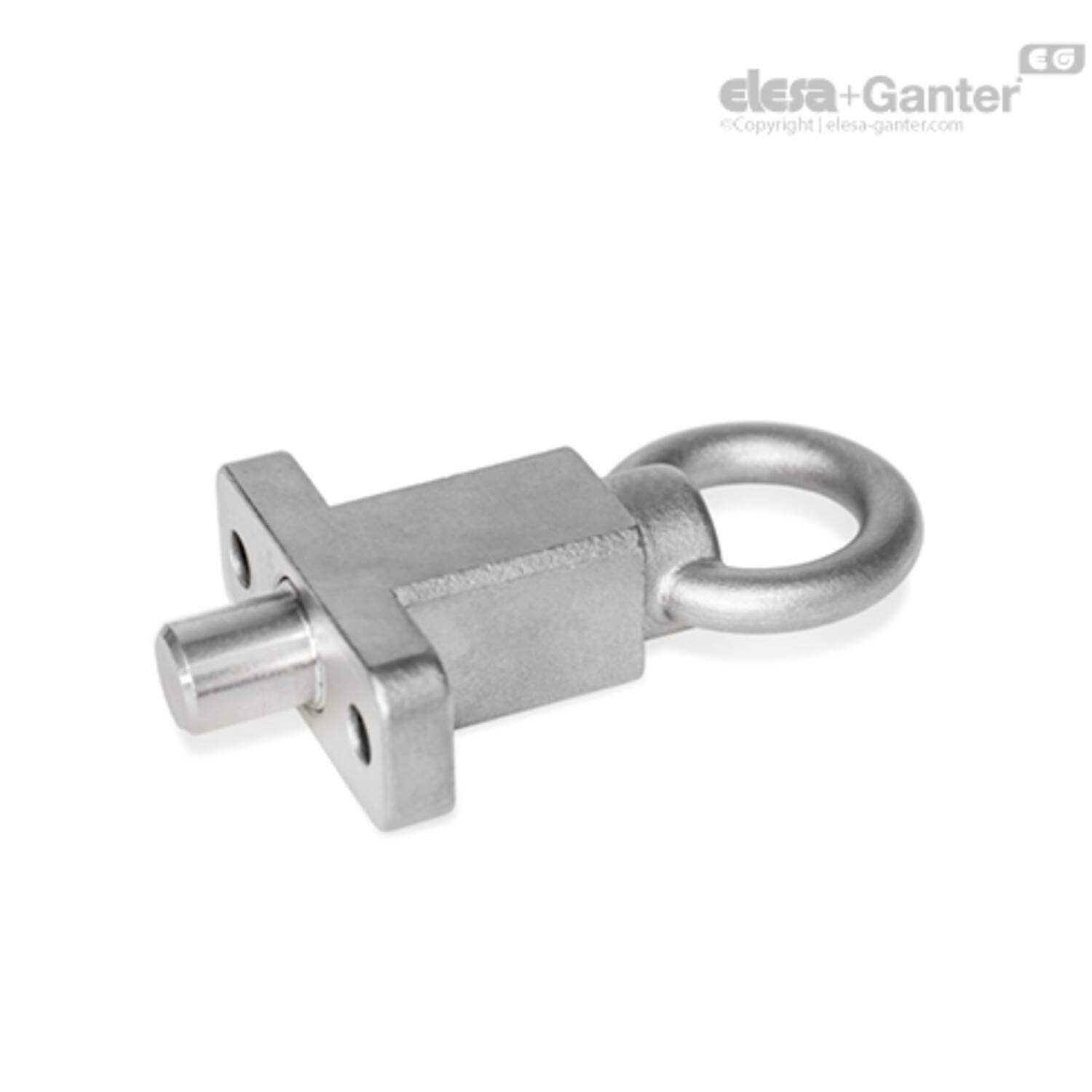
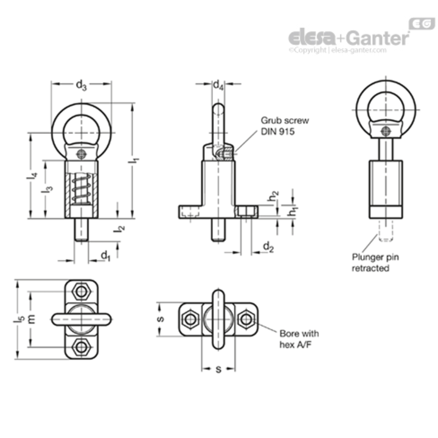


Omschrijving
Types
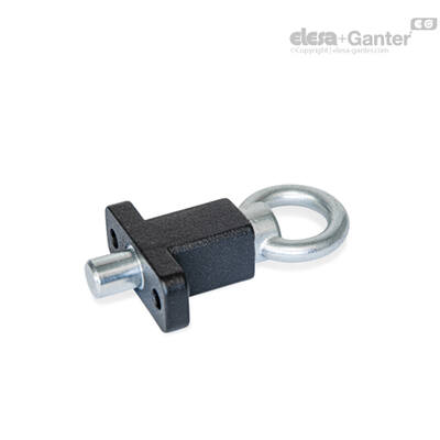
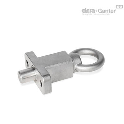
- Type A: With pull ring, without rest position
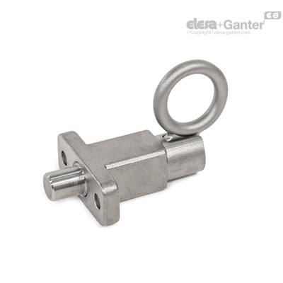
- Type C: With pull ring, with rest position
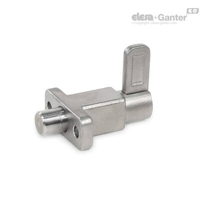
- Type E: With latch, with rest position
Guide
Steel precision casting
- Zinc plated, blue passivated ZB
- Zinc plated and powder coated
Black, RAL 9005, textured finish SW
Guide
Stainless steel precision casting AISI 316 A4
Pull ring
- Steel precision casting
Zinc plated, blue passivated (ZB and SW)
- Steel precision casting AISI 316 (for A4)
Latch
- Steel precision casting
Zinc plated, blue passivated (for ZB and SW)
- Steel precision casting AISI 316 (for A4)
Plunger Pin
- Steel precision casting
Steel, zinc plated, blue passivated (ZB and SW)
- Stainless steel AISI 316 (for A4)
Grub Screw DIN 915 (Type A)
- Steel, zinc plated (for ZB and SW)
- Stainless steel (for A4)
Pressure spring
Stainless steel AISI 316Ti
With indexing plungers GN 722.5, the plunger pin is actuated via the pull ring / latch. This is done either manually, with a cable or by means of an extended pull rod with hook. The ST version is designed for applications in steel construction, whereas the stainless steel version A4 is suitable for use in particularly aggressive environments.
The type with rest position is used when the plunger pin should temporarily not protrude. For this purpose, the pull ring is turned sideways after the locking pin has been retracted. The ring is held in this position by the catch groove at the top of the guide.
The dimensional tolerances between the pin and the guide have been chosen to ensure functional reliability even in roughly dimensioned applications or in the event of soiling.
There are several options for fastening. The hexagonal mounting holes allow the use of socket cap screws DIN 912 and hex screws or nuts according to DIN 931 or DIN 934.
Uitvoering


| Filters resetten | Filter: | ||||
Code |
Product omschrijving |
Aantal |
Prijs |
Bestel |
CAD |
|---|---|---|---|---|---|
| 470041480 | GN 722.5-10-20-A-A4 |
|
|||
| 470041483 | GN 722.5-12-20-A-A4 |
|
|||
| 470041486 | GN 722.5-14-20-A-A4 |
|
|||
| 470041489 | GN 722.5-16-30-A-A4 |
|
|||
| 470041492 | GN 722.5-20-30-A-A4 |
|
|||
| 470041495 | GN 722.5-8-20-A-A4 |
|
|||
|
|
|
|
|
|
|
|
|
|
|
|
|
|
|
|
|
|
|
h2 |
d4 |
l3 |
Gewicht (g) |
s |
Veerdruk in N2 |
l5 |
Veerdruk in N3 |
d1 Pin -0.05/-0.25 Boring +0.1/+0.3 |
l1 ≈ |
AF |
d2 +0.3 |
h1 |
l4 |
d3 |
m |
l2 |
|---|---|---|---|---|---|---|---|---|---|---|---|---|---|---|---|---|
| 1.5 | 7 | 35 | 162 | 20 | 50 | 48 | 15 | 10 | 70 | 10 | 6.1 | 7.5 | 52 | 36 | 34 | 14 |
| 1.5 | 7 | 35 | 165 | 20 | 50 | 48 | 15 | 12 | 70 | 10 | 6.1 | 7.5 | 52 | 36 | 34 | 14 |
| 1.5 | 7 | 35 | 170 | 20 | 50 | 48 | 15 | 14 | 70 | 10 | 6.1 | 7.5 | 52 | 36 | 34 | 14 |
| 5 | 10 | 54 | 703 | 30 | 110 | 80 | 30 | 16 | 103 | 17 | 10.1 | 15 | 78 | 50 | 55 | 20 |
| 5 | 10 | 54 | 721 | 30 | 110 | 80 | 30 | 20 | 103 | 17 | 10.1 | 15 | 78 | 50 | 55 | 20 |
| 1.5 | 7 | 35 | 160 | 20 | 50 | 48 | 15 | 8 | 70 | 10 | 6.1 | 7.5 | 52 | 36 | 34 | 14 |