
 Handwielen, handslingers
 Knoppen, vleugelmoeren
 Klemhendels, verstelbare handgrepen
 Beugelgrepen, handgrepen
 Vaste, draaiende handgrepen
 Control elements
 Indicatoren, klokhandwielen
 Blokkeerbouten, drukstukken
 Machine elementen
 Koppelingen, tandwielen
 Stelvoeten, stelelementen
 Scharnieren
 Vergrendelingen, deursluitingen
 Snelspanners, spansluitingen
 Hydrauliek componenten
 Tube clamp connectors
 Castors and wheels
 Magneten
 Transportband componenten
 Lineaire bewegingscomponenten
 Trillingsdempers
 Aluminium profielen
 Vacuüm componenten
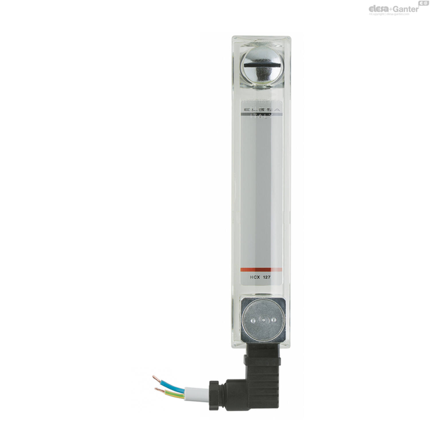
Omschrijving
Material
Transparent polyamide based (PA-T) technopolymer. Highly resistant to shocks, solvents, oils with additives, aliphatic and aromatic hydrocarbons, petrol, naphtha, phosphoric esters.
Avoid contact with alcohol or detergents containing alcohol.
Screw, nuts and washers
Zinc-plated steel.
Packing rings
NBR synthetic rubber O-Ring.
Suggested roughness of the packing ring application surface Ra = 3 µm.
Temperature electrical probe
Zinc-plated steel screw with built-in probe. The probe is made out of a platinum resistor whose ohmic resistance changes according to the temperature.
For a correct assembly see Warnings.
Swivelling two-pin connector
With built-in cable gland and contact holder. Front or side output (right or left) including protection against water sprays (protection class IP 65 according to EN 60529 table-) that can be increased during installation with the necessary adjustments. Flat NBR synthetic rubber packing rings.
Contrast screen
White lacquered aluminium. The housing, in the appropriate external rear slot, guarantees the best protection from direct contact with fluid.
It can be taken out from the inclined side, before assembly to allow the insertion of level lines or words.
Mounting
When fitting is not possible from the inside of the reservoir and the walls are not thick enough, the screws can be used together with Fast Mounting Kit-.
Maximum continuous working temperature
90°C (with oil).
Features and performances
This column level indicator generates an analogic electric signal of the oil temperature.
Ultrasound welding to guarantee a perfect seal.
Maximum fluid level visibility even from side positions.
Lens effect for a better visibility of the fluid level and temperature.
Technical data
In laboratory tests carried out with mineral oil type CB68 (according to ISO 3498) at 23°C for a limited period of time, the weld stood up to: 18 bar (HCX.127-STL) 12 bar (HCX.254-STL).
For use with other fluids and under different pressure and temperature conditions, please contact ELESA Technical Department.
In any case we suggest to verify the suitability of the product under the actual working conditions.
Functioning of the temperature electrical probe
The working principle of the temperature probe is to measure the variation of resistance of a platinum element: 100 ohm = 0°C, 138.4 ohm = 100°C.
The function between temperature (T) and resistance (R) is approximately linear over a small temperature range: for example, if you assume that it is linear over the 0° to 100°C range, the error at 50°C is 0.4°C.
For precision measurement, it is necessary to linearise the resistance to give an accurate temperature. The most recent definition of the function between resistance and temperature is International Temperature Standard 90 (ITS-90). The function between resistance and temperature, obtained in laboratory tests, measuring directly the resistance value on the contacts is shown in the graph.
We suggest, anyway, to set the system in order to compensate both heat dissipation and cable resistance.

A 1°C temperature change will cause a 0.384 ohm change in resistance, so even a small error in measurement of the resistance (for example, the resistance of the wires leading to the sensor) can cause a large error in the measurement of the temperature.
Because of the low signal levels, it is important to keep any cables away from electric cables, motors, switchgear and other devices that may emit magnetic or electrical noise. Using screened cable, with the screen grounded at one end, may help to reduce interference.
When using long cables, it is necessary to check that the measuring equipment is able to handle the cable resistance.
| Electrical features | Temperature probe |
| Tension feed | AC/DC |
| Maximum current | 2 mA |
| Cable gland | Pg 7 (for cables in sheath with Ø 6 or 7 mm) |
| Conductors cross-section | Max 1.5 mm2 |

Special executions on request
- Level indicators for use with fluids containing alcohol or with hot water.
- UV resistant transparent technopolymer indicators.
- Indicators with two red ball-shaped floats.
Two-pin connector assembly instructions
- Remove the connector from the indicator by unscrewing the set screw placed in the bottom, take the contact holder out and loosen the cable gland.
- Slip on the two-pole cable into the connector (standard connector) and connect the wires to the terminals nr. 1 and nr. 2 of the contact holder.
- Assemble by pressing the contact holder into the connector in the required position.
- Screw the connectors to the indicator and then tighten the cable glands.

| Filters resetten | Filter: | ||||
Code |
Product omschrijving |
Aantal |
Prijs |
Bestel |
CAD |
|---|---|---|---|---|---|