 Handwielen, handslingers
 Knoppen, vleugelmoeren
 Klemhendels, verstelbare handgrepen
 Beugelgrepen, handgrepen
 Vaste, draaiende handgrepen
 Bedieningselementen
 Indicatoren, klokhandwielen
 Blokkeerbouten, drukstukken
 Machine elementen
 Koppelingen
 Stelvoeten, stelelementen
 Scharnieren
 Vergrendelingen, deursluitingen
 Snelspanners, spansluitingen
 Hydrauliek componenten
 Buisklemverbindingen
 Wielen en zwenkwielen
 Magneten
 Transportband componenten
 Lineaire bewegingscomponenten
 Trillingdempers
 Aluminium profielen
 Vacuümcomponenten
HVF-E
Doorstroom indicatoren met flowmeter sensor
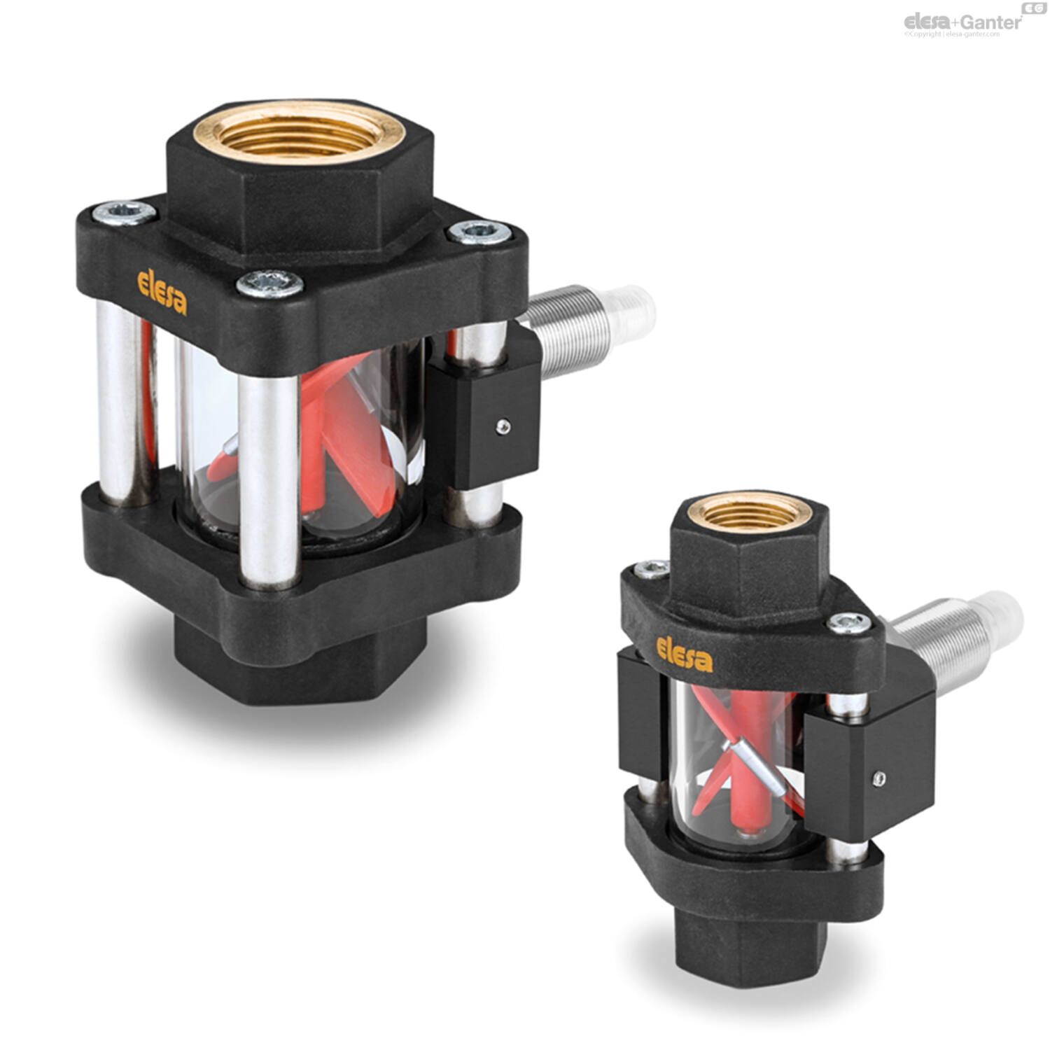
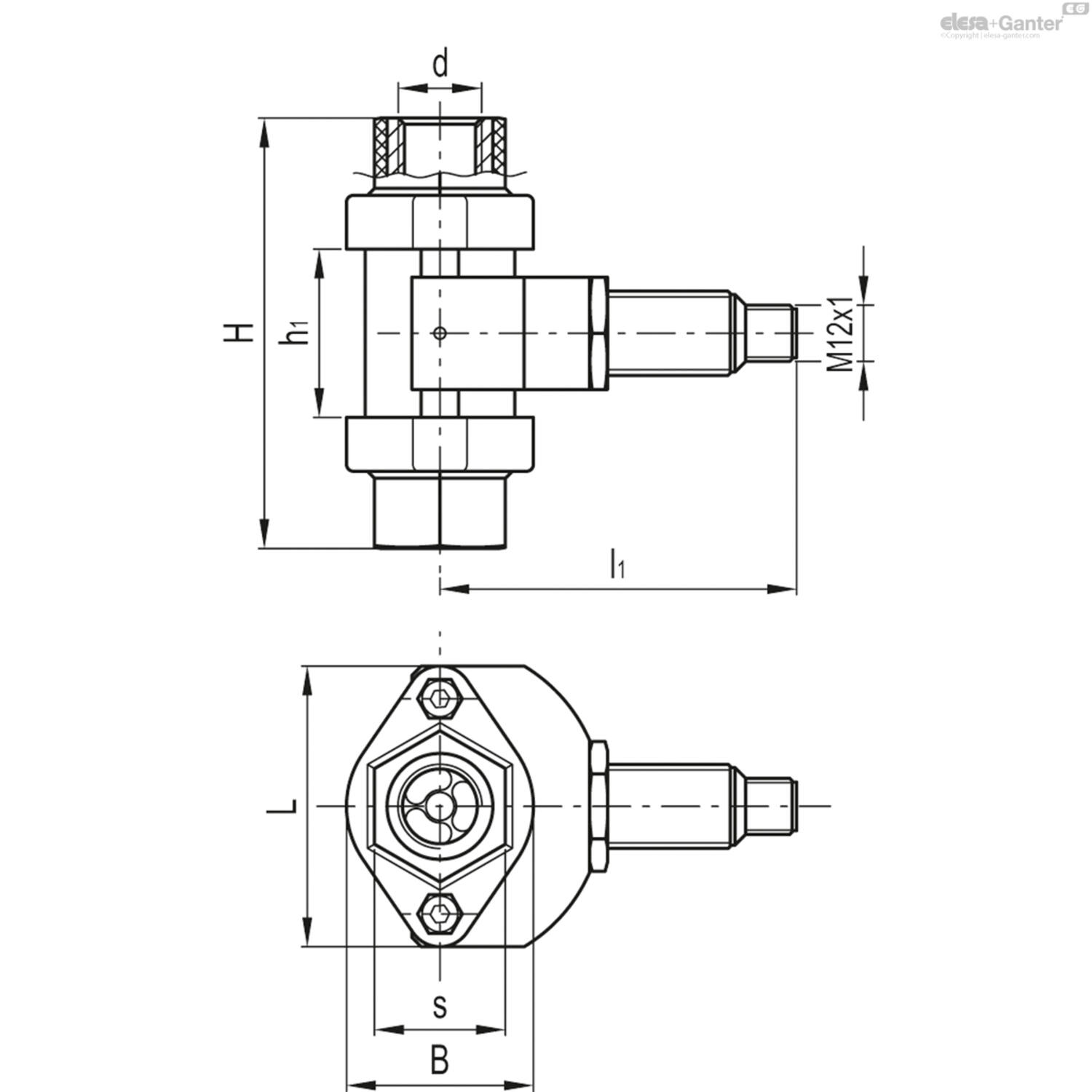

Omschrijving
Ends and sensor holder
Polypropylene based (PP) technopolymer, black colour, matte finish.
Axis and rotor propeller
Polypropylene based (PP) technopolymer, red colour. AISI 304 stainless steel sensor activating clips.
Tubular window
Borosilicate glass, high-resistance, also suitable for use with glycol-based solutions.
Sensor
Nickel-plated brass inductive sensor
Tie rods
AISI 316L stainless steel.
Packing rings
NBR synthetic rubber.
Standard execution
Brass bosses with cylindrical gas thread according to UNI ISO 228/1.
Maximum continuous working temperature
100° C.
| Sensor | Inductive |
| Power supply | 10 – 30 Vcc |
| Input | 10 mA |
| Max load | 200 mA |
| Short circuit protection | Yes |
| Reverse polarity protection | Yes |
| Output | PNP |
| Connector | M12x1 – 4 poli |
| Protection class | IP67 |


Features and applications
The indicator can be mounted in any position.
In case of mounting on rigid tubes, it is recommended to place the indicator perfectly aligned with the tubes.
The indicator operates with two-way liquid flows with a viscosity lower than 30cSt.
In order to allow the propeller rotation, a minimum flow rate is required depending on the type of fluid and its viscosity.
At the passage of the minimum flow rate, the rotor starts to rotate with a speed proportional to the fluid flow.
The inductive sensor, completely separated from the liquid passage area, reads the passage of the two metal clips mounted on the rotor, providing a frequency variation that can be transformed into a reading of the flow rate by connection to a PLC.
Assembly instructions
To ensure the correct operation of the rotor, it is necessary to wash and purge the circuit before mounting the indicator, to eliminate any particles to work in clean fluid conditions.
Since the presence of air bubbles in the fluid can give rise to measurement errors, it is advisable to mount the indicator before valves and / or other components that could create cavitation.
Measuring range
The total measuring range Q1 indicates the range between the minimum and maximum flow rate value in which the sensor provides a reading.
In the non-linear measurement range Q2 the inductive sensor provides a signal that cannot be considered accurate since the rotation of the rotor is not constant.
In the linear measuring range Q3, the pulses provide the measurement with an accuracy of ± 3%.
Both rotor wear and pressure loss increase for flow rates Q4 higher than the maximum.
The pulses per litre shown in the table represent values measured with water at 20°C and refer to average values tested with different sensors to obtain a more accurate measurement value. Compared to the value measured with water, the linear flow-frequency function can vary by ± 10% depending on the density of the liquid used or its temperature.
It is therefore recommended a specific calibration for each type of liquid used. The repeatability of the measurement is ± 3%, referred to the full scale frequency.


Special executions on request
- AISI 316 stainless steel bosses.
- Bosses with NPT conical threads.
- Axis and rotor propeller in blue colour.


Scroll onderstaande tabel om meer te zien
Code |
Product omschrijving |
Aantal |
Prijs |
Bestel |
CAD |
|---|---|---|---|---|---|
| 470033391 | HVF.92-E-1/2 111315 |
|
|||
| 470033390 | HVF.92-E-3/8 111313 |
|
|||